
CONTACT US AT
LADHANI METAL CORPORATION, MUMBAI, INDIA
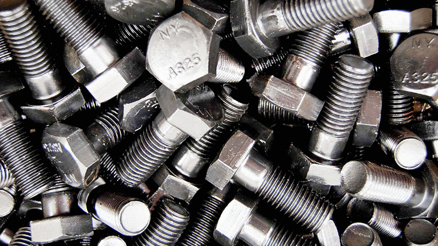
ASTM A325 Bolt Dimensions Chart, Sizes, Strength
ASTM A325 bolts are one of the most commonly used fasteners, usually used for structural steel connections in heavy steel structures. It contains two types of quenched and tempered steel heavy hex structural bolts:
- Type 1: medium carbon, carbon boron, or medium carbon alloy steel,
- Type 3: weathering steel.
- Type 2: withdrawn in 1991.
The ASTM A325 standard was withdrawn in 2016 and replaced by ASTM F3125/F3125M. Except for the dimensions, the information on this page is for reference and historical purposes only.
ASTM A325 Bolts Properties & Specification
ASTM A325 material properties and specification are list in the following tables including dimensions, sizes, strength, etc.
Chemical Requirements
| Chemical Requirements for Type 1 Bolts, Heat Analysis | ||||||||
| Grades | Material | C | Si | Mn, ≤ | P, ≤ | S, ≤ | B | Alloying Elements |
| ASTM A325 Type 1 | Carbon Steel | 0.30-0.52 | 0.15-0.30 | 0.6 | 0.04 | 0.05 | – | – |
| Carbon Boron Steel | 0.30-0.52 | 0.15-0.30 | 0.6 | 0.04 | 0.05 | 0.0005-0.003 | – | |
| Alloy Steel | 0.30-0.52 | 0.15-0.35 | 0.6 | 0.035 | 0.04 | – | A | |
| Alloy Boron Steel | 0.30-0.52 | 0.15-0.35 | 0.6 | 0.035 | 0.04 | 0.0005-0.003 | A | |
| Chemical Requirements for Type 1 Bolts, Product Analysis | ||||||||
| Grades | Material | C | Si | Mn, ≤ | P, ≤ | S, ≤ | B | Alloying Elements |
| ASTM A325 Type 1 | Carbon Steel | 0.28-0.55 | 0.13-0.32 | 0.57 | 0.048 | 0.058 | – | – |
| Carbon Boron Steel | 0.28-0.55 | 0.08-0.32 | 0.6 | 0.04 | 0.05 | 0.0005-0.003 | – | |
| Alloy Steel | 0.28-0.55 | 0.13-0.37 | 0.6 | 0.04 | 0.045 | – | A | |
| Alloy Boron Steel | 0.28-0.55 | 0.13-0.37 | 0.6 | 0.04 | 0.045 | 0.0005-0.003 | A | |
ASTM A325 Bolt Strength
ASTM A325 bolt strength are summarized in the table bellow inluding tensile strength, yield strength and hardness, etc.
Notes:
The stress area is calculated as follows:
As = 0.7854 [D-(0.9743/n)]
- As = stress area, in2,
- D = nominal bolt size, and
- n = threads per inch.
| Tensile Requirements for Full-Size Bolts, Studs, and Threaded Rod | ||||
| Bolt Size, Threads per Inch, and Series Designation | Stress Area, in. | Tensile Load, lbf, ≥ | Proof Load, Length Measurement Method | Alternative Proof Load, Yield Strength Method |
| 1/2 – 13 UNC | 0.142 | 17,050 | 12,050 | 13,050 |
| 5/8 – 11 UNC | 0.226 | 27,100 | 19,200 | 20,800 |
| 3/4 – 10 UNC | 0.334 | 40,100 | 28,400 | 30,700 |
| 7/8 – 9 UNC | 0.462 | 55,450 | 39,250 | 42,500 |
| 1 – 8 UNC | 0.606 | 72,700 | 51,500 | 55,750 |
| 1 1/8 – 7 UNC | 0.763 | 80,100 | 56,450 | 61,800 |
| 1 1/4 – 7 UNC | 0.969 | 101,700 | 71,700 | 78,500 |
| 1 3/8 – 6 UNC | 1.155 | 121,300 | 85,450 | 93,550 |
| 1 1/2 – 6 UNC | 1.405 | 147,500 | 104,000 | 113,800 |
A325 bolt grade loads tabulated are based on the following:
| Bolt Size, in. | Tensile Strength, ksi | Length Measurement Method, ksi | Yield Strength Method, ksi |
| 1/2 to 1 | 120 | 85 | 92 |
| 1 1/8 to 1 1/2 | 105 | 74 | 81 |
Hardness Requirements
| Hardness Requirements for Structural Bolts, Studs, and Threaded Rod | |||
| Bolt Size, in | Nominal Length, in. | Hardness | |
| Brinell, HB | Rockwell B | ||
| 1/2 – 1 | < 2D | 253-319 | 25-34 |
| 2D, ≥ | ≤319 | ≤34 | |
| 1 1 /8 – 1 1 /2 | < 3D | 223-286 | 19-30 |
| 3D, ≥ | ≤286 | ≤30 | |
| D = Nominal diameter or thread size. | |||
A325 Bolt Dimensions Chart
ASTM A325 bolt dimensions chart and sizes are listed in the table and drawing below.
NOTES OF PARA. IN ASME B18.2.6 -2019

| Table 2.1-1, Dimensions of Heavy Hex Structural Bolts A325 | ||||||||||
| Nominal Size or Basic Product Diameter, inch | Body Diameter (Max-Min), E | Width Across Flats, F | Width Across Corners, G | Head Height, H | Radius of Fillet, R | Thread Length, L T | Transition Thread Length, Y | Maximum Total Runout of Bearing Surface, FIM | ||
| Nominal | Max-Min | Nominal | Max-Min | |||||||
| 1/2 (0.500) | 0.515-0.482 | 7/8 | 0.875-0.850 | 1.010-0.969 | 5/16 | 0.323-0.302 | 0.031-0.009 | 1.00 | 0.19 | 0.016 |
| 5/8 (0.625) | 0.642-0.605 | 1 1/16 | 1.062-1.031 | 1.227-1.175 | 25/64 | 0.403-0.378 | 0.062-0.021 | 1.25 | 0.22 | 0.019 |
| 3/4 (0.750) | 0.768-0.729 | 1 1/4 | 1.250-1.212 | 1.443-1.383 | 15/32 | 0.483-0.455 | 0.062-0.021 | 1.38 | 0.25 | 0.022 |
| 7/8 (0.875) | 0.895-0.852 | 1 7/16 | 1.438-1.394 | 1.660-1.589 | 35/64 | 0.563-0.531 | 0.062-0.031 | 1.50 | 0.28 | 0.025 |
| 1 (1.000) | 1.022-0.976 | 1 5/8 | 1.625-1.575 | 1.876-1.796 | 39/64 | 0.627-0.591 | 0.093-0.062 | 1.75 | 0.31 | 0.028 |
| 1 1/8 (1.125) | 1.149-1.098 | 1 13/16 | 1.812-1.756 | 2.093-2.002 | 11/16 | 0.718-0.658 | 0.093-0.062 | 2.00 | 0.34 | 0.032 |
| 1 1/4 (1.250) | 1.277-1.223 | 2 | 2.000-1.938 | 2.309-2.209 | 25/32 | 0.813-0.749 | 0.093-0.062 | 2.00 | 0.38 | 0.035 |
| 1 3/8 (1.375) | 1.404-1.345 | 2 3/16 | 2.188-2.119 | 2.526-2.416 | 27/32 | 0.878-0.810 | 0.093-0.062 | 2.25 | 0.44 | 0.038 |
| 1 1/2 (1.500) | 1.531-1.470 | 2 3/8 | 2.375-2.300 | 2.742-2.622 | 15/16 | 0.974-0.902 | 0.093-0.062 | 2.25 | 0.44 | 0.041 |
A325 Nut Dimensions

| Table 3.1-1, Dimensions of Heavy Hex Nuts for Use With Structural Bolts | ||||||||
| Nominal Size or Basic Major Diameter of Thread, in. | Width Across Flats, F | Width Across Corners, G | Thickness, H | Radius of Fillet, R | Total Runout of Bearing Face FIM, Heavy Hex Nuts, Specified Proof Load | |||
| Nominal, in. | Max-Min, in. | Nominal, in. | Max-Min | <150 ksi | ≥150 ksi | |||
| 1/2 (0.500) | 7/8 | 0.875-0.850 | 1.010-0.969 | 31/64 | 0.504-0.464 | 0.031-0.009 | 0.023 | 0.016 |
| 5/8 (0.625) | 1 1/16 | 1.062-1.031 | 1.227-1.175 | 39/64 | 0.631-0.587 | 0.062-0.021 | 0.025 | 0.018 |
| 3/4 (0.750) | 1 1/4 | 1.250-1.212 | 1.443-1.383 | 47/64 | 0.758-0.710 | 0.062-0.021 | 0.027 | 0.020 |
| 7/8 (0.875) | 1 7/16 | 1.438-1.394 | 1.660-1.589 | 55/64 | 0.885-0.833 | 0.062-0.031 | 0.029 | 0.022 |
| 1 (1.000) | 1 5/8 | 1.625-1.575 | 1.876-1.796 | 39/64 | 1.012-0.956- | 0.093-0.062 | 0.031 | 0.024 |
| 1 1/8 (1.125) | 1 13/16 | 1.812-1.756 | 2.093-2.002 | 1 7/64 | 1.139-1.079 | 0.093-0.062 | 0.033 | 0.027 |
| 1 1/4 (1.250) | 2 | 2.000-1.938 | 2.309-2.209 | 1 7/32 | 1.251-1.187 | 0.093-0.062 | 0.035 | 0.030 |
| 1 3/8 (1.375) | 2 3/16 | 2.188-2.119 | 2.526-2.416 | 1 11/32 | 1.378-1.310 | 0.093-0.062 | 0.038 | 0.033 |
| 1 1/2 (1.500) | 2 3/8 | 2.375-2.300 | 2.742-2.622 | 1 15/32 | 1.505-1.433 | 0.093-0.062 | 0.041 | 0.036 |
A325 Washer Dimensions

Table 4.1.1-1, Dimensions for Hardened Steel Circular and Circular Clipped Washers
| Basic Size or Nominal Washer Size, inch | Inside Diameter, I.D. | Outside Diameter, O.D. | Thickness, T | Minimum Edge Distance, E | ||
| Nominal | Max-Min | Nominal | Max-Min | Max-Min | ||
| 1/2 (0.500) | 0.531 | 0.531-0.563 | 1.063 | 1.031-1.095 | 0.097-0.177 | 0.438 |
| 5/8 (0.625) | 0.688 | 0.688-0.720 | 1.313 | 1.281-1.345 | 0.122-0.177 | 0.547 |
| 3/4 (0.750) | 0.813 | 0.813-0.845 | 1.469 | 1.437-1.501 | 0.122-0.177 | 0.656 |
| 7/8 (0.875) | 0.938 | 0.938-0.970 | 1.750 | 1.718-1.782 | 0.136-0.177 | 0.766 |
| 1 (1.000) | 1.063 | 1.063-1.085 | 2.000 | 1.937-2.063 | 0.136-0.177 | 0.875 |
| 1 1/8 (1.125) | 1.188 | 1.188-1.251 | 2.250 | 2.187-2.313 | 0.136-0.177 | 0.984 |
| 1 1/4 (1.250) | 1.375 | 1.375-1.438 | 2.500 | 2.437-2.563 | 0.136-0.177 | 1.094 |
| 1 3/8 (1.375) | 1.500 | 1.500-1.563 | 2.750 | 2.687-2.813 | 0.136-0.177 | 1.203 |
| 1 1/2 (1.500) | 1.625 | 1.625-1.688 | 3.000 | 2.937-3.063 | 0.136-0.177 | 1.313 |
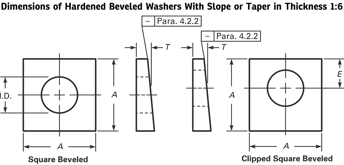
| Table 4.2.1-1, Dimensions of Hardened Beveled Washers With Slope or Taper in Thickness 1:6 | |||||
| Basic Size or Nominal Washer Size, inch | Inside Diameter, I.D. | Minimum Side Length, A | Thickness, T | Minimum Edge Distance, E | |
| Nominal | Max-Min | ||||
| 1/2 (0.500) | 0.531 | 0.531-0.563 | 1.75 | 0.313 | 0.438 |
| 5/8 (0.625) | 0.688 | 0.688-0.720 | 1.75 | 0.313 | 0.547 |
| 3/4 (0.750) | 0.813 | 0.813-0.845 | 1.75 | 0.313 | 0.656 |
| 7/8 (0.875) | 0.938 | 0.938-0.970- | 1.75 | 0.313 | 0.766 |
| 1 (1.000) | 1.125 | 1.125-1.188 | 1.75 | 0.313 | 0.875 |
| 1 1/8 (1.125) | 1.250 | 1.250-1.313 | 2.25 | 0.313 | 0.984 |
| 1 1/4 (1.250) | 1.375 | 1.375-1.438 | 2.25 | 0.313 | 1.094 |
| 1 3/8 (1.375) | 1.500 | 1.500-1.563 | 2.25 | 0.313 | 1.203 |
| 1 1/2 (1.500) | 1.625 | 1.625-1.688 | 2.25 | 0.313 | 1.313 |
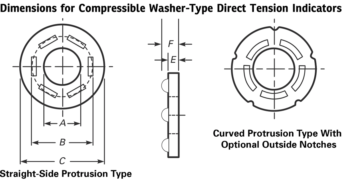
| Table 5.1-1, Dimensions for Compressible Washer-Type Direct Tension Indicators, inch | ||||||
| Direct Tension Indicator Size | All Types | Types 325-1, 325-3 | Types 490-1, 490-3 | |||
| Inside Diameter, A (Min-Max) | Protrusion Tangential Diameter, B, ≤ | Thickness, Without Protrusion, E, ≥ | With Protrusion, F, ≤ | Outside Diameter, C (Min-Max) | Outside Diameter, C (Min-Max) | |
| 1/2 (0.500) | 0.520-0.527 | 0.788 | 0.104 | 0.18 | 1.031-1.187 | 1.031-1.375 |
| 5/8 (0.625) | 0.651-0.658 | 0.956 | 0.126 | 0.22 | 1.281-1.375 | 1.281-1.625 |
| 3/4 (0.750) | 0.783-0.790 | 1.125 | 0.126 | 0.24 | 1.437-1.625 | 1.437-1.750 |
| 7/8 (0.875) | 0.914-0.921 | 1.294 | 0.142 | 0.26 | 1.718-1.875 | 1.718-2.000 |
| 1 (1.000) | 1.043-1.052 | 1.463 | 0.158 | 0.27 | 1.937-2.000 | 1.937-2.250 |
| 1 1/8 (1.125) | 1.174-1.183 | 1.631 | 0.158 | 0.28 | 2.187-2.250 | 2.187-2.500 |
| 1 1/4 (1.250) | 1.306-1.315 | 1.800 | 0.158 | 0.28 | 2.437-2.500 | 2.437-2.750 |
| 1 3/8 (1.375) | 1.437-1.446 | 1.969 | 0.158 | 0.28 | 2.687-2.750 | 2.687-3.000 |
| 1 1/2 (1.500) | 1.568-1.577 | 2.138 | 0.158 | 0.28 | 2.937-3.000 | 2.937-3.250 |
Dimensions of Twist-Off-Type Structural Bolts

| Table 6.1.1-1, Dimensions of Twist-Off-Type Structural Bolts: Heavy Hex Head and Round Head Configurations | |||||||||||||
| Nominal Size or Basic Major Diameter or Thread and Threads per Inch | Heavy Hex Head | Heavy Heit and Round Head | Round Head | Radius of Fillet, R (Max-Min.) | Thread Length, Lr | Spline Length, Ls | Spline Width Across Flats, S | Maximum Center of Groove to First Fully Formed Thread, U | Transition Thread Length, Y | Maximum Total Runout of Bearing Surface FIM, | |||
| Width Across Flats, F (Max-Min.) | Width Across Corners, G (Max-Min.) | Head Height, H (Max-Min.) | Full Size Body Dia. E (Max-Min.) | Head Dia. D, ≤ | Bearing Dia. C, ≥ | ||||||||
| 1/2 – 13 (0.500) | 0.875-0.850 | 1.010-0.969 | 0.323-0.302 | 0.515-0.482 | 1.126 | 0.89 | 0.031-0.009 | 1.00 | 0.50 | 0.32 | 0.192 | 0.19 | 0.016 |
| 5/8 – 11 (0.625) | 1.062-1.031 | 1.227-1.175 | 0.403-0.378 | 0.642-0.605 | 1.313 | 1.102 | 0.062-0.021 | 1.25 | 0.60 | 0.43 | 0.227 | 0.22 | 0.019 |
| 3/4 – 10 (0.750) | 1.250-1.212 | 1.443-1.383 | 0.483-0.455 | 0.768-0.729 | 1.58 | 1.338 | 0.062-0.021 | 1.38 | 0.65 | 0.53 | 0.25 | 0.25 | 0.022 |
| 7/8 – 9 (0.875) | 1.438-1.394 | 1.660-1.589 | 0.563-0.531 | 0.895-0.852 | 1.88 | 1.535 | 0.062-0.031 | 1.50 | 0.72 | 0.61 | 0.278 | 0.28 | 0.025 |
| 1 – 8 (1.000) | 1.625-1.575 | 1.876-1.796 | 0.627-0.591 | 1.022-0.976 | 2.158 | 1.771 | 0.093-0.062 | 1.75 | 0.80 | 0.7 | 0.313 | 0.31 | 0.028 |
| 1 1/8 – 7 (1.125) | 1.812-1.756 | 2.093-2.002 | 0.718-0.658 | 1.149-1.098 | 2.375 | 1.991 | 0.093-0.062 | 2.00 | 0.90 | 0.8 | 0.367 | 0.34 | 0.032 |
| 1 1/4 – 7 (1.250) | 2.000-1.938 | 2.309-2.209 | 0.813-0.749 | 1.277-1.223 | 2.76 | 2.213 | 0.093-0.062 | 2.00 | 1.00 | 0.9 | 0.367 | 0.38 | 0.035 |
FOR MORE DETAIL CONTACT US AT :-
LADHANI METAL CORPORATION, MUMABAI, INDIA,